
Actuated gripper
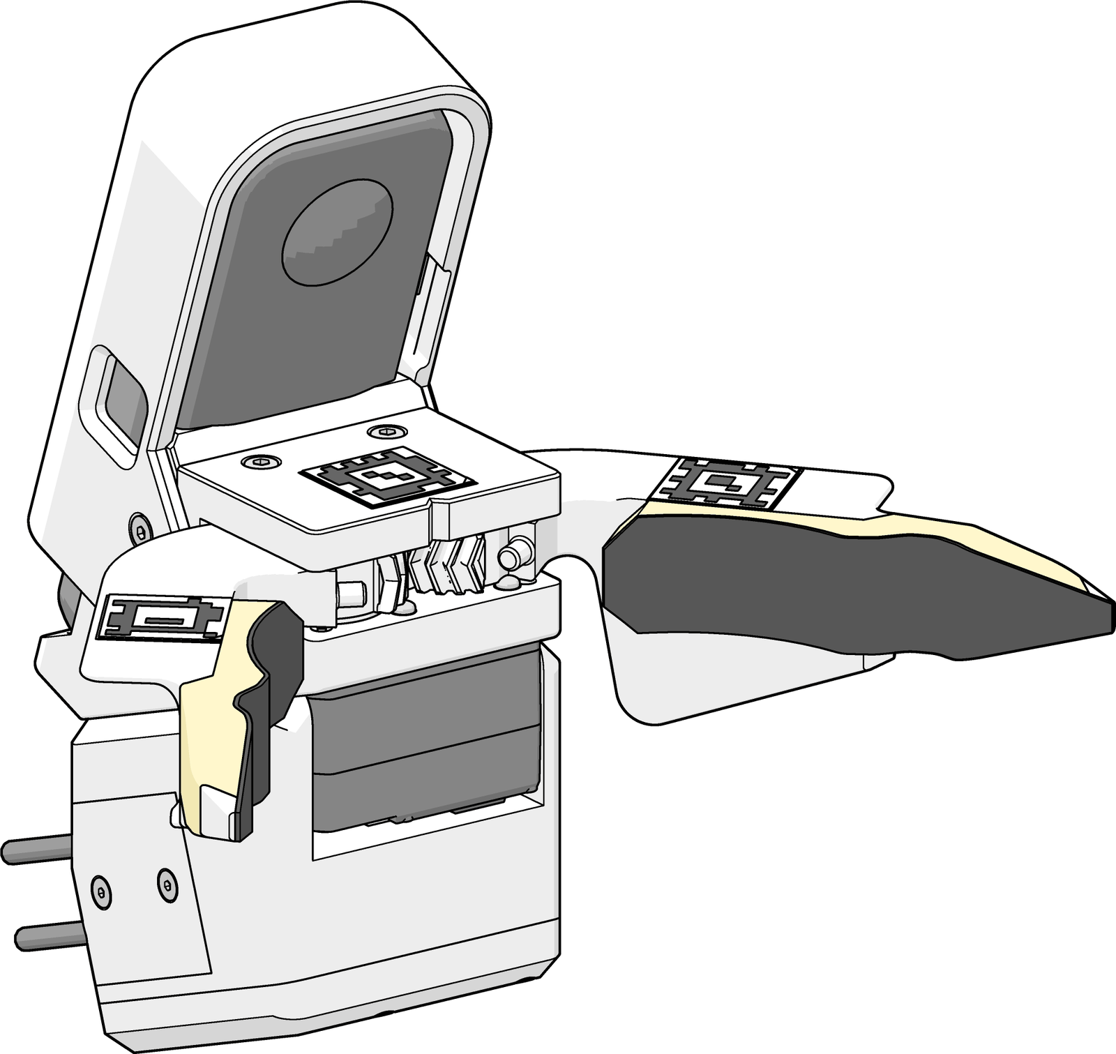
Actuated variant of the gripper for policy deployment on robot arms.
- Printed parts
- 11
- Steps
- 18
- ≈ 7.5 h
- Assembly
- ≈ 20 min
Before you start
Tools
- 3D printer for PLA and TPU 95A
- Hex keys, 1.5, 2.0 and 2.5 mm
- Phillips (PH) screwdriver
- Soldering iron
Soft tips
The tip nuts sit in soft TPU.
Tighten the M3×10 screws until the tip does not move. Do not tighten them more.
Servo first
Before you attach the horn, set the servo ID and center the servo (step 4).
Power
The driver board supplies 12 V to the servo. The computer supplies power to the hub and the camera.
Tags
Left-hand gripper: 2000 base, 2001 left finger, 2002 right finger.
Right-hand gripper: 2003 base, 2004 left finger, 2005 right finger.
Print the tags from the tag sheet at the end. Before you cut them, check their size.
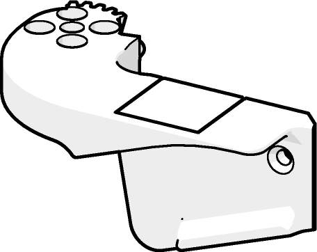
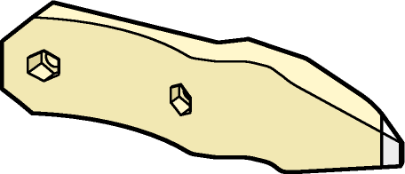

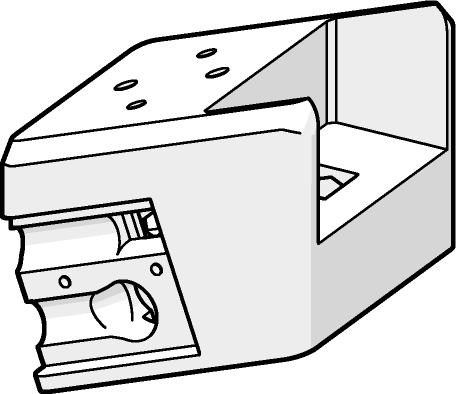
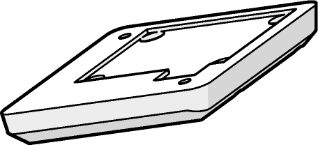
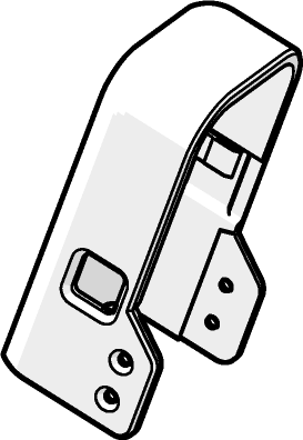
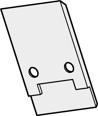
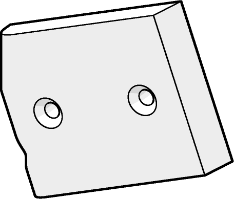
Two-material tips
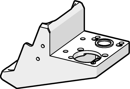
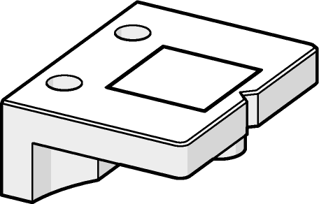
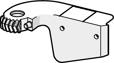
Tips E and F each have a PLA nail at the front end and a TPU 95A body.
In the slicer, import each tip as one object with two parts.
Assign PLA to the nail and TPU 95A to the body.
Set the infill of the body to 100 %.
Get the print plates on MakerWorld, or download the STEP files of the printed parts. The CAD is on Onshape.
Hardware
| Drawing | Part | Qty |
|---|---|---|
 | M3×25ISO 4762 | 4× |
 | M3×12ISO 4762 | 4× |
 | M3×10ISO 10642 | 4× |
 | M3×8ISO 10642 | 4× |
 | M2.5×16ISO 10642 | 6× |
 | M2.5×8ISO 10642 | 4× |
 | M3 nutISO 4032 | 8× |
 | 2×6 self-tappingIn the STS3215 box · for the base | 4× |
 | M3×6 pan headIn the STS3215 box · for the horn | 1× |
The drawings show all hardware at one scale. The PDF shows it at 1:1.
Buy
You also need
- Insta360 X3
- 3M TB641 grip tape
- 12 V supply with bare-wire output
Wiring
- Solder each USB-C socket lead to one downstream port of the hub.
- Connect each wire to the pad with the same name, not the same position.
- 5V
- D−
- D+
- GND
These are the usual USB 2.0 wire colors. If your lead has other colors, use its seller's pinout.
Assembly
Finished
Templates
Print from the PDF
Grip tape
- Print page 17 of the PDF at 100 %.
- Cut the 3M TB641 tape along the dashed lines.
Outline F is the mirror image of outline E.
AprilTags
- Print page 18 of the PDF at 100 %.
- Check the tag size.
- Cut along the gray lines.
The tags are tagStandard41h12. Each sticker is 20 mm square.
Check the tag size
- Measure the inner square of a printed tag. It must be 10.00 mm.
- Measure the whole tag. It must be 18.0 mm.
- If a value is different, print the tag sheet again at 100 % (Actual size). Do not use Fit to page.
A different value means that the printer changed the scale.